

Client Name: ADVANTAGEMENT
Reference Model: 151426_50-2010 CF-005829 AMB_Advantagement_JOB 5000125
Test Model: 120911_50-2010CF-005829 AMB_Advantagement_JOB 5000125
Alignment Statistics
Alignment Name: Best fit alignment: 151426_50-2010 CF-005829 AMB_Advantagement_JOB5000125 (1)
Average Error: 0.001615022 in
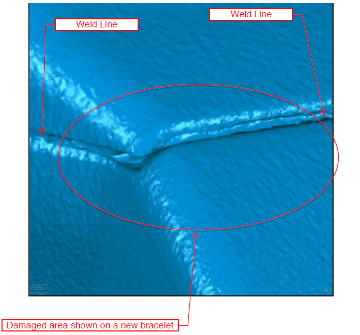
TOP-REAR CORNER, AS WORN (DAMAGED BRACELET)
Figure 1

TOP-REAR CORNER, AS WORN (NEW BRACELET)
Figure 2
TOP-REAR CORNER, AS WORN (BRACELET OVERLAY)
Figure 3

The color scale represents the amount of difference from the NEW bracelet to the DAMAGED bracelet. Green means that the NEW and DAMAGED bracelet are within +/- 0.003″ of each other.
0.003″ is the thickness of a standard sheet of paper.
The damaged area is blue in color which means the surface of the DAMAGED bracelet is below the surface of the NEW bracelet. There is no deformation around the damage that would indicate the use of a tool to create the “chip” of missing material. There is also no deformation to the tabbed area of the top piece that overhangs the weld line, further indication that the chip was not forcibly made using a tool.
TOP, AS WORN (BRACELET OVERLAY)
Figure 4

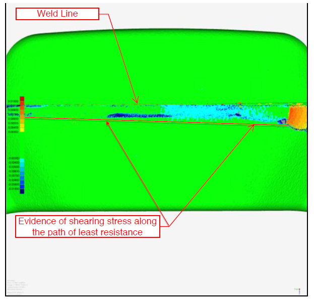
If the bracelet was pulled apart from the damaged corner the force would follow the path of least resistance, in this case the material tore along the bottom side below the weld line. The tearing indications start and end at the weld line corner where the strap extension begins (As Shown in Figure 3).
BOTTOM, AS WORN (BRACELET OVERLAY)
Figure 5
If the bracelet was pulled apart from the damaged corner the force would follow the path of least resistance, in this case the material tore along the top side below the weld line. The tearing indications start and end at the weld line corner where the strap extension begins (As Shown in Figure 3).
OUTSIDE FACE, AS WORN (BRACELET OVERLAY)
Figure 6
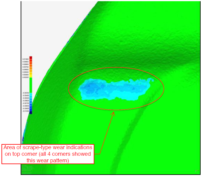
The scrape wear was determined to be from abrasion sustained by the tennis court surface.
The depth of this abrasion is 0.004″-0.007″. The thickness of 2 sheets of paper.
Even a small area of wear/damage is clearly visible when compared to a new bracelet.
SECTION A-A THROUGH CENTER OF “CHIP” FROM TOP TO BOTTOM
Figure 7

Units: in CSYS: World CSYS
| Name | Measured |
|---|---|
| D1 | 0.01730 |
| D2 | 0.09351 |
| D3 | 20.55123 |
The size of the chip is 0.094″ wide and 0.017″ deep, at a 20 degree angle relative to the weld line.
The edge is raised slightly and non-uniform.
See dimensions D1, D2 & D3 in Figure 7.
SECTION A-A THROUGH CENTER OF “CHIP” FROM FRONT TO BACK
Figure 8
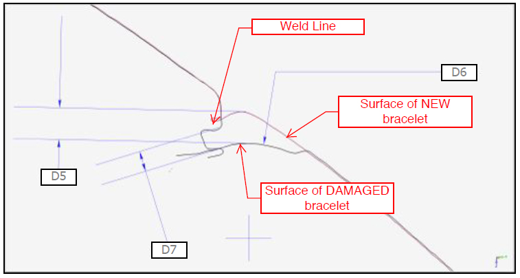
Units: in CSYS: World CSYS
| Name | Measured |
|---|---|
| D5 | 0.02732 |
| D6 | 0.08139 |
| D7 | 0.01758 |
The size of the chip is 0.081″ wide and has a convex radial floor, 0.018″-0.027″ deep.
The edge is non-uniform and non-symmetric.
This mark could not have been made with a pointed tool or the floor profile would be concave, not convex.
See dimensions D5, D6 & D7 in Figure 8.
THE INFORMATION CONTAINED IN THIS DOCUMENT IS PRIVILEGED AND CONFIDENTIAL. IT IS INTENDED ONLY FOR THE USE OF THE ENTITY NAMED ABOVE. YOU ARE HEREBY NOTIFIED THAT ANY DISSEMINATION, DISTRIBUTION OR COPYING OF THIS DOCUMENT IS STRICTLY PROHIBITED.